A Comprehensive Guide to CAM in CNC Machining
Most CNC machining processes are complex because even small parts play an important role in the production cell and therefore require careful design. Gone are the days of manually troubleshooting process issues. Today, computer-aided manufacturing, or CAM for short, is widely used to automate the manufacturing process. CAM is one of the important aspects of computer numerical control (CNC) machining, and Fusion 360 Machining Extension is emerging as the best choice. Freedom Machining is one such machine shop with CNC and CAD/CAM capabilities.
Today, manufacturers rely heavily on the power of CAM to produce high-quality and precise parts. Now, you might be interested to know what is CAM, or what components are required for CAM to function? This article answers the same question.
1.What is CAM in CNC Machining?
CAM is a program or tool that creates detailed instructions (G-code) using numerical control or NC. This code, when executed, helps CNC machines perform the desired operations such as cutting and drilling. With CNC machining, these repetitive tasks can be done easily, accurately, and precisely; regardless of the quantity. CAM is often used in conjunction with Computer Aided Design (CAD), which helps in machining even complex designs.
2.What are the components of CAM?
The industrial revolution benefited the manufacturing industry in many ways, and the introduction of CAM was one of those benefits. By definition, a CAM system requires the following three components:
- Software that instructs the machine on how to make a product by simply generating tool paths.
- Machinery that transforms raw materials or parts into finished products.
- Post-processing that can encrypt tool paths into machine code.

3.Detailed explanation of the CAD to CAM process
As mentioned earlier, CAD/CAM software designs and manufactures prototypes. CAM works in conjunction with CAD to produce finished products directly from computer designs. CAD prepares product designs, while CAM supports prototyping and assembly line production.
Step 1
First, engineers prepare product drawings in a 2D or 3D modeling program. This prototype contains a set of physical properties that are further used by the CAM system.
Step 2
The prototype is then imported into CAM software, which prepares the model for machining through a variety of operations such as drilling and cutting.
Step 3
In order to perform machining efficiently, a set of English instructions is converted into a language called G-code. G-code contains all the instructions that control the machine’s actions, including machine speed, feed rate, and coolant. Once the G-code is loaded, the machine will begin executing the prototype into a finished product.

4.How does CNC machining utilize CAM?
We have covered all about CAD and CAM systems. Now, it is time to look at how CNC machining utilizes CAM software.
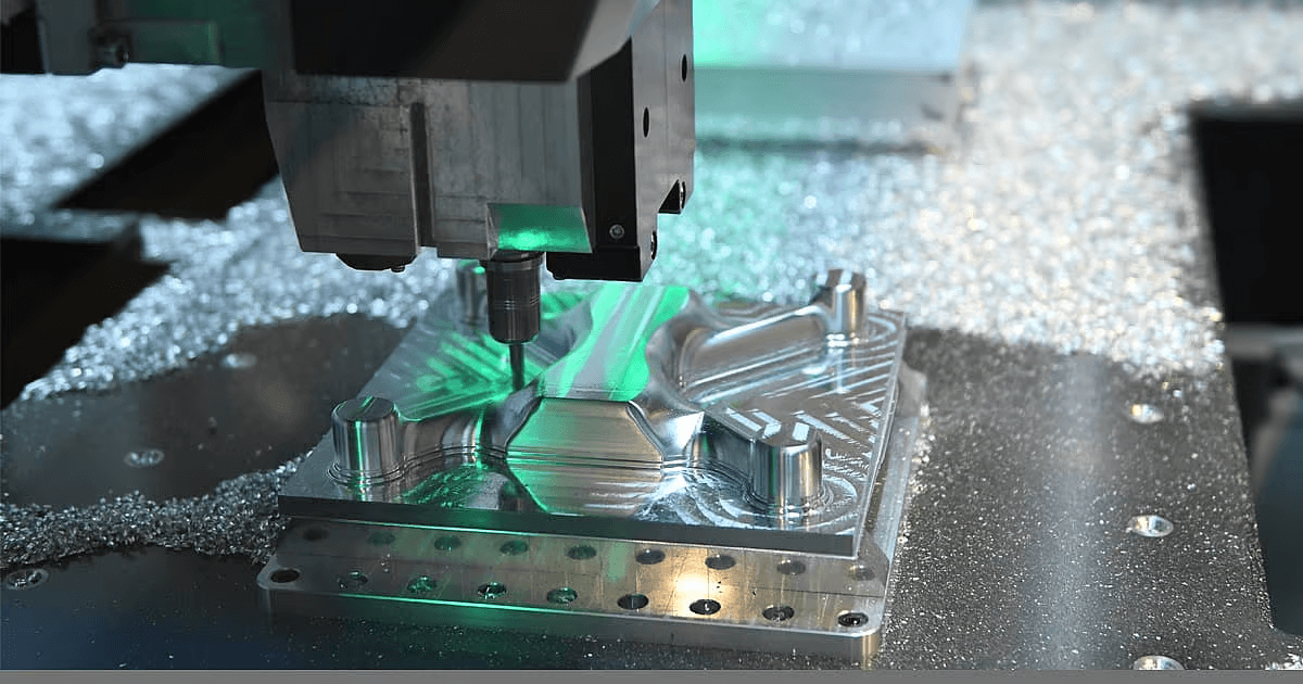
In a typical workflow, a programmer selects a drawing of a CAD model and analyzes the processes and tools required to manufacture or assemble the desired part. The individual is responsible for defining the tool paths, speeds, and feeds in the G-code. This program is then handed over to the machine operator who configures the CNC machine by loading the G-code program and setting up the tools. Once the system is ready to run, the machine will begin executing the tasks it was programmed to perform.
Now you may have understood the role of CAD/CAM software in the manufacturing process. It provides designers with greater control over part size, design complexity, flexibility, etc.
