What is cutting speed? How is it calculated?
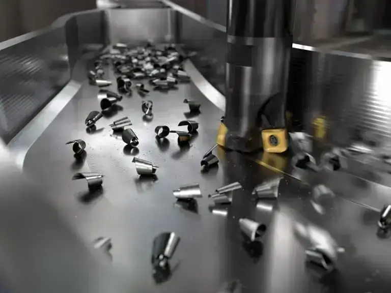
In CNC machining, cutting speed is considered one of the core parameters affecting machining efficiency and quality. Whether turning, milling, or drilling, the relative speed between the tool and the material surface directly determines the efficiency of material removal, the rate of tool wear, and the final finish of the workpiece.
For the manufacturing industry, which strives for high precision and stability, properly matching cutting speed is not just a technical requirement; it is also crucial for improving productivity and reducing costs.
Table of Contents
1.What is cutting speed?
Cutting speed (Vc) is one of the most important process parameters in machining. It is generally defined as the linear velocity of the tool cutting edge relative to the workpiece surface. In other words, it indicates the relative speed of the workpiece surface and the contact point of the tool per unit time. The faster the cutting speed, the higher the metal removal rate.
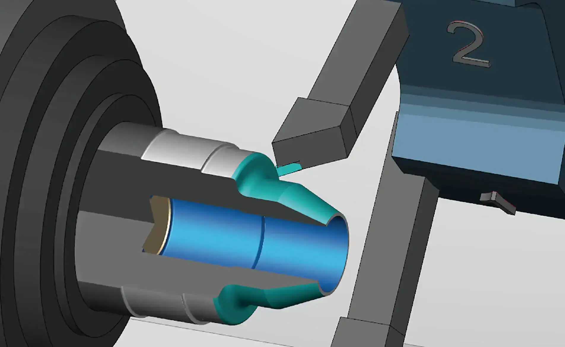
Common units are meters per minute (m/min) or surface feet per minute (SFM). In lathe machining, it refers to the speed of the workpiece surface relative to the tool; in milling and grinding machines, it refers to the speed of the tool’s cutting edge relative to the workpiece surface.
Cutting speed has a decisive influence on tool life, machining temperature, power consumption, surface finish, and overall machining efficiency. Selecting the appropriate cutting speed can significantly improve productivity, extend tool life, and avoid rapid tool wear due to excessively high speeds or inefficient cutting due to excessively low speeds.
In actual production, cutting speeds are often provided by tool manufacturers based on the machinability of different materials. However, the final selection should also consider the following factors:
● Surface type (roughing or finishing)
● Workpiece material and its mechanical properties
● Machine tool and fixture rigidity
● Machining efficiency and cost requirements
Therefore, cutting speed is not just a parameter in a formula; it is a core variable that influences the quality and economic efficiency of the entire CNC machining process.
2.How to Determine the Appropriate Cutting Speed?
Determining cutting speeds isn’t a one-size-fits-all approach. There are several common methods you can use as a reference:
Check the tool manufacturer’s recommendations
Many tool manufacturers provide recommended cutting speeds, derived from testing and experience. Obtaining the tool’s manual and following the recommended settings will usually provide a good starting point.
Calculating with a Formula
Cutting speeds can also be calculated using a formula. Knowing the workpiece/tool diameter and spindle speed will yield an appropriate speed. Even if you have limited machining experience, these calculators can help you quickly arrive at a reasonable reference value.
Practical Trial
Sometimes the most reliable method is to test the process yourself. Start with a lower speed and gradually increase it to see if the surface finish meets your requirements or if the tool wear occurs. While this method is more time-consuming, it will help you find the speed that works best for your machine, tool, and material.
Using Rules of Thumb
There are also some commonly used industry guidelines. For example, when machining steel, approximately 100 SFM is a good starting point. However, the specific speed should be adjusted based on the type of steel and your desired surface finish.
3.Cutting Speed Calculation Formula and Principle
Formula Reasoning:
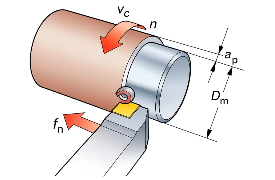
During metal turning, the tool removes a circle of material for each spindle rotation. This circumferential length can be expressed as: Cutting Length = π × D
Where: π = 3.14 (constant); D = workpiece or tool diameter (unit: mm).
If the spindle rotates two times, the cutting length = 2 × π × D.
Similarly, for n spindle rotations, the cutting length = π × D × n.
Thus, the cutting speed formula is:
Cutting Speed Vc = (π × D × N) ÷ 1000 (unit: m/min)
Where: Vc = cutting speed (m/min); D = workpiece/tool diameter (mm); N = spindle speed (rpm).
Note: Since diameter D is usually expressed in millimeters, it must be divided by 1000 to convert to meters per minute.
Reverse formula:
Conversely, if the cutting speed Vc and workpiece diameter D are known, the required spindle speed can be calculated:
Spindle speed N = (1000 × Vc) ÷ (π × D) (unit: rpm)
Example 1:
Calculate the cutting speed when machining a 25 mm diameter cylinder at 4500 rpm.
Given: D = 25 mm, N = 4500 rpm
Calculation:
Vc = (π × D × N) ÷ 1000
= (3.14 × 25 × 4500) ÷ 1000
= 353.25 m/min
Answer: The cutting speed is approximately 353.25 m/min.
Example 2:
Given the cutting speed Vc = 120 m/min, calculate the spindle speed when machining a 20 mm diameter cylinder.
Given: Vc = 120 m/min, D = 20 mm
Calculation:
N = (1000 × Vc) ÷ (π × D)
= (1000 × 120) ÷ (3.14 × 20)
= 1910.82 rpm
Answer: The spindle speed is approximately 1911 rpm.
4.What is feed rate? What is the difference between feed rate and cutting speed?
The machining feed rate is the speed at which the tool advances along the workpiece during machining, or the distance the tool moves per spindle revolution. In milling, it is usually expressed in mm/min or in/min; in turning or boring, it is expressed in mm/rev or in/rev. In grinding, feed rates are usually expressed in mm/min or in/min.
The feed rate is influenced by factors such as the tool material (such as metal, ceramic, or high-speed steel), the workpiece material (such as stainless steel, mild steel, aluminum, or wood), the machine tool’s performance, and the desired surface finish. Feed rate not only affects machining efficiency, but also directly determines the smoothness and appearance of the part surface. When calculating the feed rate, machinists will combine the number of teeth on the tool to determine the amount of material cut by each tooth, thereby optimizing the machining effect.
Through the above introduction to feed rate, do you think its definition is very similar to that of cutting speed? Yes, these two parameters are easy to confuse. But in fact, in machining, they are two important but different parameters. The following will compare feed rate and cutting speed in detail:
(1) Differences in definition
Cutting speed refers to the speed at which the cutting edge of the tool passes over the surface of the workpiece, that is, the relative linear speed generated when the blade cuts the material; while feed rate is the speed at which the tool or workpiece advances during the cutting process, that is, the rate at which the tool continues to advance to continue cutting. The former emphasizes “how fast the blade cuts”, while the latter emphasizes “how fast the tool moves”, and the two play different roles in the machining process.
(2) Difference in units
Cutting speed is usually expressed in surface speed. Common units include surface feet per minute (SFM) or feet per minute (ft/min) or meters per minute (m/min), which are used to describe the linear speed of the cutting edge relative to the workpiece; while the feed rate is inches per revolution (IPR) or millimeters per revolution (mm/rev) in turning; and inches per minute (IPM) or millimeters per minute (mm/min) in milling. The two have different dimensions and measurement objects – one is “linear speed” and the other is “feed distance/rate”.
(3) Difference in main influencing points
Cutting speed mainly affects tool life, cutting zone temperature and machine power consumption; feed rate mainly determines material removal rate, processing time and final surface finish (especially grain and scallop marks). Cutting speed can be regarded as a “regulator of heat and wear” and feed rate as a “metronome of surface quality and efficiency”.
(4) Differences in influencing factors
The appropriate value of cutting speed is affected by the hardness of the workpiece material, tool material, cutting depth and expected tool life; the feed rate is more constrained by factors such as tool type (number of teeth, number of grooves), required surface roughness, cutting width (RDOC), and processing method.
(5) Differences in the impact on cutting temperature and tool life
Cutting speed has the greatest impact on cutting temperature and tool wear: increasing speed will significantly increase the temperature of the cutting zone and accelerate wear; feed rate has little effect on temperature, but high feed will make the chips thicker and the friction greater, thereby indirectly shortening tool life through mechanical load and friction.
(6) Differences in the impact on surface finish
The impact of cutting speed on surface quality is mostly indirect (manifested through chip morphology, vibration and material deformation); while feed rate directly determines the spacing of surface lines and the depth of scallop marks: the greater the feed, the wider the line spacing and the higher the roughness; when the feed is very small, the chips are extremely thin, which may also cause another type of surface defect.
(7) Differences in the impact on cutting force and power consumption
Cutting speed is closely related to machine power consumption and instantaneous power (at a certain cutting depth/feed, increasing linear speed often increases power consumption); feed rate directly affects instantaneous cutting force through chip load and material removal rate – feed and cutting depth together determine the cutting cross section, and thus the magnitude of the force.
(8) Differences in geometric analogy
From the perspective of geometric motion, cutting speed is equivalent to the generatrix (the path in the circumferential or cutting direction) “swept” by the blade on the workpiece, while feed rate is equivalent to the guideline generated by the tool’s advancement (the trajectory of the tool’s advancement along the workpiece). The superposition of the two determines the actual cutting trajectory of the tool in space.
(9) Differences in motion types
Cutting speed comes from cutting motion (usually generated by spindle rotation or relative linear motion); feed rate belongs to feed motion (linear advancement). The two work synchronously to complete an effective cutting.
(10) Calculation
| Physical Quantity | Formula |
| Cutting Speed | V_c = (π×D×n)/1000 |
| Spindle Speed | n = V_c ÷ π ÷ D × 1000 |
| Feed | V_f = n × f_z × Z |
| Feed per Tooth | f_z = V_f/(n×Z) |
5.Six important factors affecting cutting speed
(1) Machining Materials
Different materials have different hardness and characteristics, which directly affects their cutting speed. Harder materials, such as stainless steel or titanium, require lower speeds to prevent excessive tool wear and maintain dimensional accuracy. On the other hand, softer materials, such as aluminum or plastic, can be cut at higher speeds without affecting the quality of the finished product.
(2) Types of Cutting Tools
Since different cutting tools have different capabilities and limitations, this determines the maximum speed at which they can operate effectively. For example, carbide cutting tools are known for their high-speed capabilities and can withstand higher cutting speeds than high-speed steel tools. Therefore, carefully consider the choice of cutting tool material and design to ensure compatibility with the required speed.
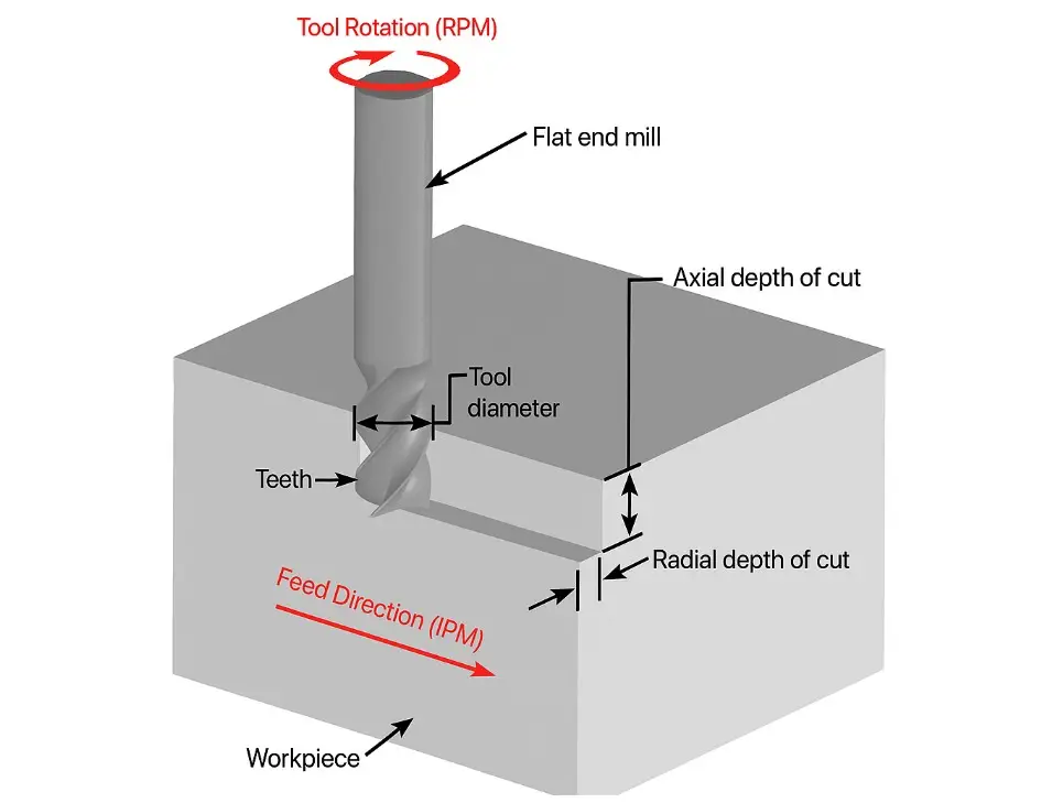
(3) Depth of Cut
Depth of cut refers to the thickness of material removed in a single cut. Increasing the depth of cut allows for higher cutting speeds, as more material can be removed per revolution of the cutting tool. However, it is critical to strike a balance between depth of cut and cutting speed to avoid excessive tool wear and potential damage to the workpiece.
(4) Rigidity of Machine Tool and Workpiece Setup
A stable and rigid setup enables higher cutting speeds because it minimizes vibrations and ensures precise cutting. On the other hand, a weak or unstable setup can lead to chatter, poor surface finish and reduced tool life.
(5) Cutting Fluids
Cutting fluids have many purposes, including cooling the cutting tool and workpiece, lubricating the cutting zone and flushing away chips. By reducing heat and friction, cutting fluids can increase cutting speeds and extend tool life. Cutting fluid selection should be based on the material being machined and the specific machining operation to optimize speed and overall performance.
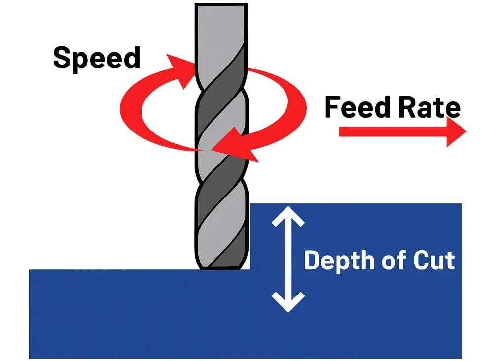
(6) Feed Rate
This refers to the speed at which the cutting tool advances along the workpiece. The higher the feed rate, the faster the cutting speed because more material is removed per unit time. However, the limitations of the cutting tool and workpiece material must be considered to avoid excessive tool wear or damage.
6.How to match cutting speed with specific materials?
Before officially commencing machining, it’s crucial to properly set various process parameters, with cutting speed being the most crucial. Cutting speed can be understood as the rate at which material is removed. Together with other parameters like feed rate and lathe or milling machine spindle speed, it determines machining efficiency and quality.
Different materials have varying sensitivity to cutting speeds, which explains why the recommended speeds for machining steel and aluminum differ significantly. Even within aluminum alloys, for example, there are variations between series. The parameters for milling a 2xxx series mill will differ from those for a 7xxx series mill, a fact often readily apparent to experienced operators.
When using new cutting tools, operators need to pay close attention to the manufacturer’s recommended parameters and verify and adjust them during actual machining. Although cutting tool manufacturers often provide reference Vc values for specific materials, flexible adjustments based on experience and observation often achieve better results.
It is important to note that there is a direct relationship between cutting speed and workpiece surface hardness: the harder the material, the lower the recommended Vc value should be. Generally speaking, the reference range generally recognized in the industry is:
In short, the selection of cutting speed should be based on the material hardness, combined with the specific alloy properties and surface finish requirements, and then fine-tuned through actual processing feedback to achieve efficient and stable processing results.
Summary:
In summary, cutting speed settings cannot be generalized; instead, they should be considered comprehensively, taking into account material properties, tool performance, and machining objectives. By scientifically selecting cutting speed and feed rate, operators can find the optimal balance between tool life and surface quality, achieving an efficient, stable, and economical machining process.
With Xavier, you no longer have to worry about complex machining parameters like cutting speed and feed rate. With extensive industry experience and advanced CNC machining equipment, our professional team can fully leverage our manufacturing advantages to create high-precision parts that meet your design standards and quality requirements. Feel free to contact us to discuss your CNC machining project with our engineering experts!

FAQs:
CNC Terminology: Cutting Speed, Feed Rate, Spindle Speed, and Feed Per Tooth
● Spindle Speed (RPM): The speed at which the spindle rotates.
● Cutting Speed (SFM or m/min): The speed at which the tool’s cutting edge moves across the workpiece surface. This has the greatest impact on tool life. Excessive speeds can cause rapid tool wear.
● Feed Rate (IPM or mm/min): The speed at which the tool advances into the material. This directly affects surface quality and machining completion time.
● Feed Per Tooth (IPT or mm/t, for milling): The amount of material removed per tooth per revolution, used to calculate the total feed rate.
How can a beginner quickly determine if the cutting speed is appropriate?
● Observe the chip and tool condition:
● If the chips are overheated and bluish-black → The speed is too high.
● If the chips stick to the tool or the workpiece surface is rough → The speed may be too low.
● If the tool edge breaks quickly → The speed and feed may not be matched.
Is cutting speed related to coolant use?
Yes. Using coolant reduces cutting zone temperatures, allowing for higher cutting speeds and extending tool life. This is particularly important for difficult-to-machine materials such as stainless steel and titanium alloys.
Do cutting speeds need to be adjusted specifically for five-axis machining or high-speed milling?
Yes. In high speed milling or multi-axis machining, due to variations in cutting methods, engagement angles, and tool loads, actual speeds often need to be optimized based on machine capabilities and workpiece characteristics, rather than relying solely on standard recommendations.