Difference between Fillet Machining and Chamfer Machining
What is the difference between fillet machining and chamfer machining? If you’ve ever thought about creating a product design that’s manufactured using a CNC machine or 3D printer, you’ve no doubt thought about this question. A fillet is described as a rounded corner, while a chamfer is described as a beveled corner of a part. But the answer to this question goes beyond just the shape of the machined part. As a product designer, you need to first understand the functional differences between these features and the ideal design scenarios for these features. This article covers all of that and more.
1.What is the difference between fillet machining and chamfer machining?
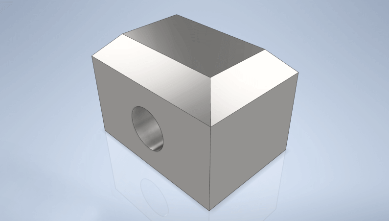
A fillet is a rounded corner of a design (or part) that helps reduce stress and prevents rapid deformation at the corners of a part. Conversely, a chamfer is a sloped or angled edge (usually 45° or 60°) of a design or part. Like fillets, chamfers also help smooth out sharp edges, reduce stress concentrations, and increase the load-bearing capacity of machined parts. However, chamfers have higher stress concentrations (or are less able to resist stress) because they don’t spread stress over a wider surface like fillets do.

Both fillets and chamfers can improve the aesthetics of a part. However, chamfered edges are more forgiving when it comes to product design; you can easily incorporate them into almost any part without worrying about increasing manufacturing costs and the functionality of the part.
2.Two Things to Remember When Making Fillets
1) CNC Machining Bottom Edges
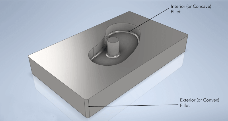
Consider the illustration below, where we have a cuboid part with a cavity that has an internal (or concave) fillet and an external (or convex) fillet.
Bottom edges (concave corners) like these are particularly challenging to manufacture using CNC machines because they require specialized tools like ball end mills. Not only will this increase your manufacturing costs, but it may also cost you more lead time because ball end mills are fragile and have slower cutting speeds. Therefore, you may be better off implementing a square bottom feature.

However, if the functionality of your design requires a fillet on the bottom edge, you may want to consider using an additive 3D printing process to create your part.
2) Designing the Internal Edges Between Vertical Walls to Create Fillets
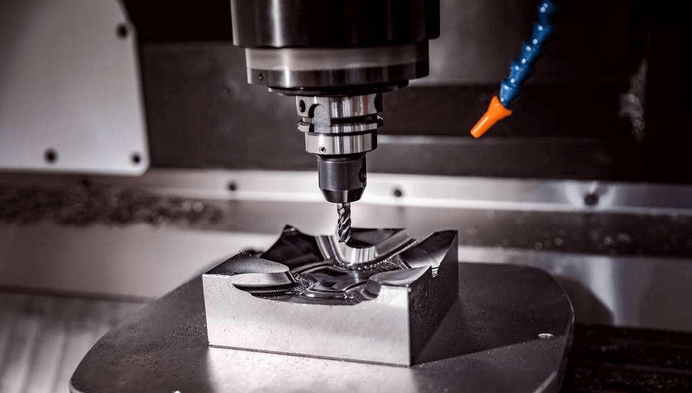
The subtractive nature of CNC milling is such that it always creates fillets (or fillets) between the vertical walls of a cavity. The size of these fillets depends on the size of the end mill used for the milling operation. For example, an end mill with a size (or diameter) of 0.8 mm can create fillets with a radius size as small as 0.4 mm. Therefore, if you want to create a cavity with this end mill, you cannot achieve a fillet with a radius size of 0.2 mm.
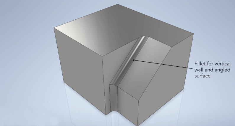
Similarly, the size of the end mill tool also needs to be considered when designing fillets in areas where vertical walls intersect curved (or angled) walls, as shown in the figure.

Remember that the length of an end mill is a standard multiple of its diameter. We always recommend using an end mill that is 3 to 5 times longer than its diameter to get the most out of your CNC machine.
3.Creating Fillets and Chamfers: Xavier Precision Machining Can Help
Now that you understand the functional differences between fillets and chamfers, you can easily decide which one to include in your product design to reduce high stress concentrations and improve aesthetics. However, the success of a manufactured part still depends largely on your machining partner.
