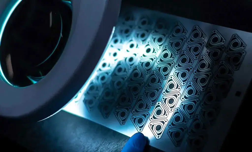
Photochemical machining: The ultimate guide to taking advantage
Photochemical machining is a cost-effective manufacturing process and engineered machining solution and machining services tailored to the needs of the chemical industry. Whether undertaking simple design projects, such as packaging covers for electronic circuit boards, or projects with more advanced specifications and tight tolerances.
Photochemical machining offers design engineers the advantages of low-cost tooling, rapid prototyping, and high-precision, tight tolerance capabilities. There are a variety of metal fabrication processes to choose from in the manufacturing industry, but photochemical machining is a proven solution for prototyping and producing quality thin metal parts.
This post will help you understand photochemical machining, how it works, its applications, and why you should consider it when designing manufacturable parts.
1.What is photochemical machining?
Photochemical machining is a machining technique that utilizes photographic and chemical processes to produce engineered design parts for a variety of industries. Other names for the photochemical machining process include photochemical milling, photoetching, chemical machining, acid etching, and metal etching.
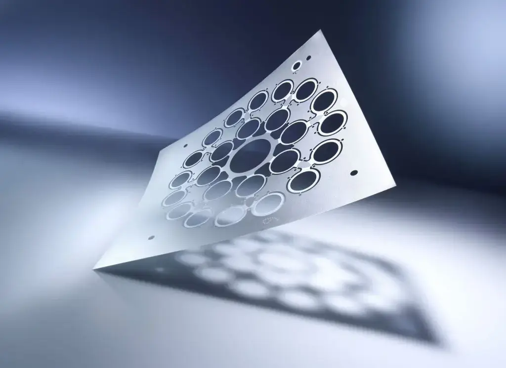
2.How does photochemical machining work?
Photochemical machining begins with cleaning a flat sheet of metal material to remove oils and contaminants. The material is then laminated on both sides using an acid-resistant photopolymer film. Photoresist is applied to the laminated metal sheet and UV light is used to expose the pattern to the laminate on both sides of the metal.
The final pre-etch preparation process is a developer solution that selectively removes excess photoresist from unprotected areas, leaving only the part pattern.
Using a conveyor belt etcher, ferric chloride is used to dissolve the unprotected areas, leaving only the desired portions.
After the etching process, the finished parts are placed in a stripping solution to remove any remaining photoresist and a corrosion inhibitor is applied to prevent rust and oxidation.
The etched parts are free of any contaminants and are then ready for further processing and/or final quality control.
3.Commonly used metals in photochemical machining
The following metals and metal alloys are commonly used in the photochemical machining process:
- Stainless steel alloys
- Steel alloys
- Brass
- Copper
- Beryllium copper
- Aluminum
- Inconel
- Nickel silver
- Phosphor bronze
- Exotic alloys
4.What is photochemical machining used for?
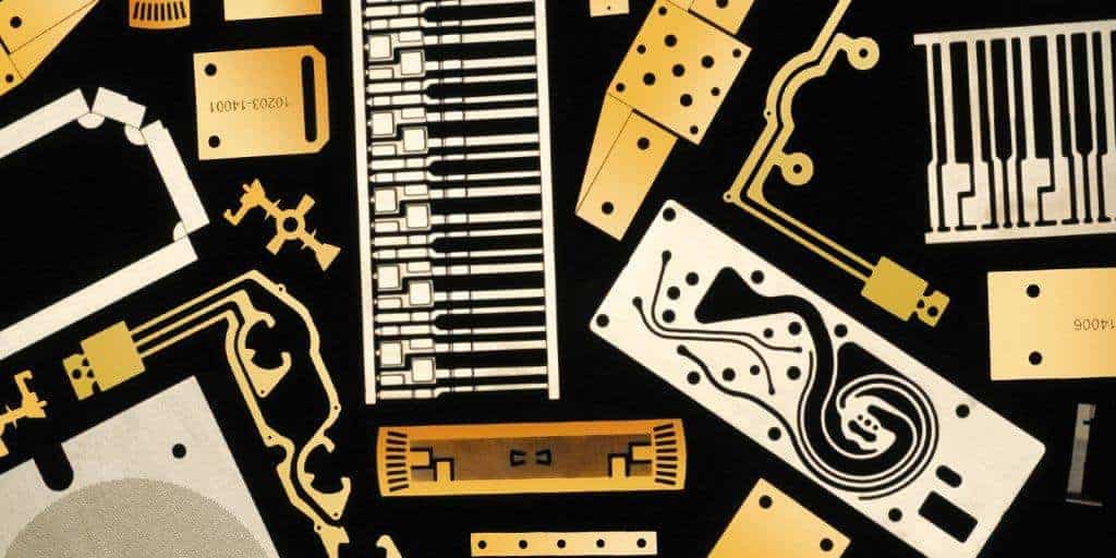
Etched products are commonly used in a variety of consumer products. Because etched parts are so versatile, you can find them in items as small as cell phones and as large as airplanes.
Photochemical machining products can exist on their own or in products such as:
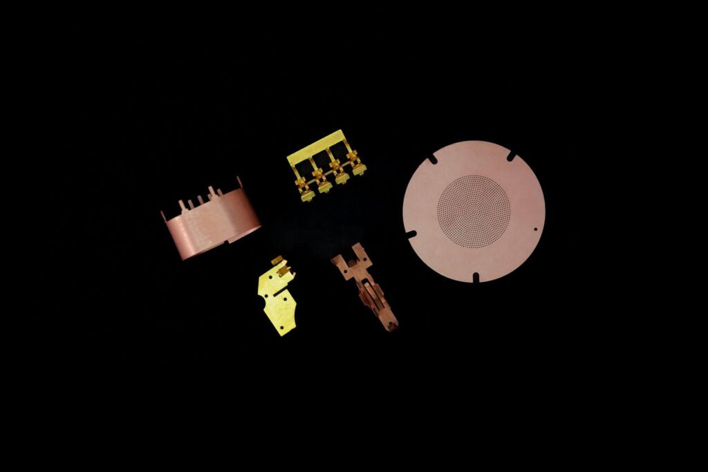
1) Electronics and Hardware
- Fine Screening
- Sensors
- Metal Gaskets
- Circuit Components
- Washers
- Apertures
- Microwave/Telecommunications
- Cell Phones
- Hearing Aids
2) Medical Devices
- Imaging Equipment
- Surgical Blades
- Medical Batteries
- Pacemakers
- Microscope Objectives
3) Aerospace
- Telescopes
.2 Radars
- RF Signal Collectors
Any application that requires a thin gauge sheet metal fabrication solution should consider photochemical machining.
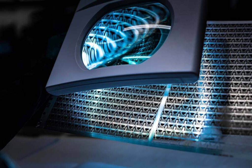
5.What are the benefits of photochemical machining?
1) Low-cost Tools
Photochemical machining utilizes polyester film with silver-based ink as a tool to transfer the image. The typical cost of an engineering tool for the photochemical machining process is about $400. The tool can also be generated or modified/regenerated within 1-2 business days.
In contrast, traditional stamping or tool-based manufacturing methods can cost thousands of dollars and require considerable preparation time from start to first application.
2) Preservation of Metal Properties
Unlike traditional machining, photochemical machining does not produce jagged edges or wear and preserves the physical properties of the metal. This process does not affect the hardness, grain structure or ductility of the metal because no mechanical force is applied to the metal.
Because the process does not involve heating the part, there is no heat-affected zone like other traditional machining methods.
3) Versatility in Prototyping
With photochemical machining, you can make multiple changes to the part during the prototyping process, and designers or manufacturers can change dimensions with low-cost tools. A single tool can also be used to create multiple styles of potential designs.
4) Burr-free parts
The photochemical machining process is capable of producing burr-free products. Features such as etched holes and separation edges will be smooth, rounded and burr-free.
5) Reproducibility of Design
Photochemical machining allows the pattern to be replicated multiple times on the panel, reducing costs and maintaining design accuracy.
6) Recessing of Material Thickness
Photochemical machining, often referred to as “half etching,” allows material to be removed from only one side of the sheet. This allows for multiple depths throughout the designed part. This can be used as text identification, bend lines for post-processing, recessed dimples, or general surface finishing and roughness.
6.Disadvantages of Photochemical Machining
While photochemical machining offers many advantages, as with any metalworking process, there are some limitations. PCM works best with relatively thin materials, typically less than 0.1 inches (2.5 mm) thick. This means that the process may not be suitable for producing thicker parts.
The size of parts produced using PCM is also limited. This is because the size of the metal sheet is limited by the width of the chemical etcher used.
While PCM is a cost-effective and fast process for producing high-precision parts with complex geometries, it may not be suitable for mass production of three-dimensional or simpler parts. This is because traditional sheet metal processing processes generally offer more favorable production time and unit cost calculations.
7.Photochemical Machining Part Design Guidelines
Photochemical machining is a manufacturing technique that uses chemical reactions to precisely remove material from a metal sheet. A light-sensitive mask, called a photoresist, is applied to the metal surface, protecting the areas where the material is to remain.
The metal sheet is then exposed to UV light and goes through a developing process that hardens the masked sections. Finally, the unprotected metal is dissolved from the frame, leaving behind the desired part or component.
Accurate design is critical for machining to ensure precise material removal and achieve the intended component specifications. Any discrepancies can result in errors in the final product, affecting its functionality and compromising the overall quality of the etched component.
Below are different design principles and guidelines to ensure the best results:
1) Tolerances
Standard rules for tolerances are critical to achieving consistent results across different manufacturing scales. In the early stages of product development, a ±20% tolerance on metal thickness balances precision and flexibility. This allows for iterative adjustments without compromising the viability of the etching process.
Given the variability of prototype development, designers should be prepared to optimize tolerances based on feedback from initial runs. This adaptability ensures that subsequent iterations meet evolving design specifications. Prototyping also typically involves smaller batches, and tolerance selection should be aligned with cost considerations.
As designs transition from prototyping to full production, tight tolerance control is recommended. While ±20% may be adequate for prototyping, high-volume production requires tighter control to ensure consistent part quality.
2) Center-to-Center Dimensions
Center-to-center distance refers to the distance between the center points of two adjacent features, such as holes, slots, or other geometric elements. Small items can utilize photochemical processing to closely match the dimensions outlined in the production design. Due to certain limitations in the preparation process, actual tolerances are critical to guide the manufacturing process.
3) Hole Size and Slot Width
As a general rule, the diameter of a hole or the width of a slot should not be less than 1.2 times the thickness of the metal. This guideline prevents over-etching and material deformation, which can occur if the features are too small relative to the object. Adhering to this guideline helps maintain the mechanical strength of the metal and ensures consistent results during etching.
4) Line Width
When using metals less than 0.005 inches thick, the line width must be equal to the thickness to prevent deformation. For objects wider than 0.005 inches, guidelines recommend a line width of at least 1.2 times the thickness of the metal. This relationship ensures that the etching process proceeds without sacrificing the strength of the metal structure and produces accurate and reliable components.
5) Corner Radius and Hole Configuration
Here are a few considerations to enhance the repeatability and reliability of components:
- Inside Corner Radius
Sharp inside corners can be difficult to achieve and can cause material deformation or irregularities during the etching process. Therefore, utilize adequate inside corner radius to promote smoother etching and prevent stress concentration.
- Outside Corner Radius
Maintain adequate outside corner radius to prevent undercutting, which is the phenomenon where the etchant corrodes the metal beyond the desired edge. Adequate outside radius facilitates a more controlled etching process, ensuring that the component maintains its intended shape.
- Hole Configuration
Consider the hole arrangement and configuration of the design. Proper separation between these features prevents material bridging and ensures that each hole is etched individually. This is especially important in designs with many slots or similar elements.
6) Bevel
Bevel in photochemical machining refers to the slope created on the hole wall or metal edge during the etching process. The general practice is to etch evenly from both sides, or completely from one side to simplify the operation. When engraving on both sides is required, the designer can vary the depth to create more bevel on one side.
The variation is quantified by specifying the percentage of etching on each side. For example, 90/10 means 90% machining on one side and 10% etching on the other side. The indicated etching percentages allow for some leeway given the complexity of this operation. This will account for the practical challenges of obtaining an accurate bevel.
7) Tie-offs or Tabs
Tie-offs or tabs extend one or more lines from a part to the metal border. Their size and number are usually minimized unless otherwise specified. This practice maintains the structural integrity of the part during etching. In cases where the part is very small, tabs can help strip photoresist or facilitate electroplating operations.
